
There has been a lot of talk on changing Air Fuel Ratios when the ECU is operating in closed loop. Here is my spin on the subject.
The Problem:
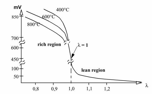
If the ECU does not see 450mV-600mV it will keep on changing the mixture until it gets to 450mV-600mV. If it cant get there it will go into limp home mode.
For example lets say the Heated Exhaust Gas Oxygen (HEGO) sensor voltages are:
![Image]()
1.20 50mV lean
1.10 60mV lean economy
1.05 70mV economy
1.00 450mV stoichiometric (14.7:1)
0.90 750mV power
0.85 800mV rich power
0.80 850mV rich
As you can see the HEGO has a very narrow band of opperation. There is very little voltage difference between economy/lean and power/rich.
![Image]()
So when the ECU is in closed loop this is what we want it to see for us to achieve maximum economy.
1.20 50mV lean
1.10 450mV lean economy
1.05 600mV economy
1.00 750mV stoichiometric (14.7:1)
0.90 750mV power
0.85 800mV rich power
0.80 850mV rich
Here is the difference between the HEGO and ideal.
1.20 0mV lean
1.10 +390mV lean economy
1.05 +530mV economy
1.00 +300mV stoichiometric (14.7:1)
0.90 0mV power
0.85 0mV power
0.80 0mV rich
There is no linear relationship here. A resistor, linear amplifier or constant voltage will not be able to change the HEGO to ideal.
The problem with using a digital microcontroller interceptor and narrow band HEGO is that the voltage differences are so small that a change in temperature will change the tune significantly.
I dont even think an "aftermarket chip" would change the closed loop AFR.
Maybe someone with a Unichip could test this for us?
Solution:
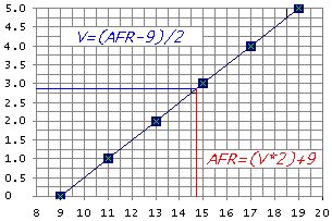
We will use a wideband AFR meter. Most of these units have an analogue output where voltage is proportional to the AFR. Here is an example:
![Image]()
Here is a rough circuit i quickly made up:
![Image]()
50mV is always connected to the ECU.
450mV is switched on at >3.5V equivalent of 15.5:1 (lambda 1.05)
800mV is switched on at >3.75V equivalent of 16:1 (lambda 1.09)
The result will be that at cruise the ECU will try and keep the AFR between lambda 1.05 and 1.09.
The switch is so that it can go back to stock easily. This means you can use the wideband AFR meter on yuor other cars!
Here: http://wbo2.com is a really good wideband AFR meter for only $355 if you DIY.
This is a handy little project that will tell you when the ECU is in closed loop.
Autospeed - Closed Loop Monitor:
http://www.autospeed.com.au/cms/A_1716/article.html?popularArticle
Reference Threads.
http://www.fordforums.com/showthread.php?t=82794
http://www.fordforums.com/showthread.php?t=81718
It will probly be about 1/3 of the price of an EMS 8860 or Unichip
Do you guys think this will work?
ps) Now that you have a wideband AFR meter you can reduce the fuel pressure. This will bring your AFR from 0.75 lambda or worse back to 0.85 lambda. You will get an increase in power and economy when the computer is reading off its stored fuel maps. You will have fully functional closed loop mode too.
pps) do you have to change the timing when running lean?
The Problem:
If the ECU does not see 450mV-600mV it will keep on changing the mixture until it gets to 450mV-600mV. If it cant get there it will go into limp home mode.
For example lets say the Heated Exhaust Gas Oxygen (HEGO) sensor voltages are:
1.20 50mV lean
1.10 60mV lean economy
1.05 70mV economy
1.00 450mV stoichiometric (14.7:1)
0.90 750mV power
0.85 800mV rich power
0.80 850mV rich
As you can see the HEGO has a very narrow band of opperation. There is very little voltage difference between economy/lean and power/rich.

So when the ECU is in closed loop this is what we want it to see for us to achieve maximum economy.
1.20 50mV lean
1.10 450mV lean economy
1.05 600mV economy
1.00 750mV stoichiometric (14.7:1)
0.90 750mV power
0.85 800mV rich power
0.80 850mV rich
Here is the difference between the HEGO and ideal.
1.20 0mV lean
1.10 +390mV lean economy
1.05 +530mV economy
1.00 +300mV stoichiometric (14.7:1)
0.90 0mV power
0.85 0mV power
0.80 0mV rich
There is no linear relationship here. A resistor, linear amplifier or constant voltage will not be able to change the HEGO to ideal.
The problem with using a digital microcontroller interceptor and narrow band HEGO is that the voltage differences are so small that a change in temperature will change the tune significantly.
I dont even think an "aftermarket chip" would change the closed loop AFR.
Maybe someone with a Unichip could test this for us?
Solution:
We will use a wideband AFR meter. Most of these units have an analogue output where voltage is proportional to the AFR. Here is an example:
Here is a rough circuit i quickly made up:

50mV is always connected to the ECU.
450mV is switched on at >3.5V equivalent of 15.5:1 (lambda 1.05)
800mV is switched on at >3.75V equivalent of 16:1 (lambda 1.09)
The result will be that at cruise the ECU will try and keep the AFR between lambda 1.05 and 1.09.
The switch is so that it can go back to stock easily. This means you can use the wideband AFR meter on yuor other cars!
Here: http://wbo2.com is a really good wideband AFR meter for only $355 if you DIY.
This is a handy little project that will tell you when the ECU is in closed loop.
Autospeed - Closed Loop Monitor:
http://www.autospeed.com.au/cms/A_1716/article.html?popularArticle
Reference Threads.
http://www.fordforums.com/showthread.php?t=82794
http://www.fordforums.com/showthread.php?t=81718
It will probly be about 1/3 of the price of an EMS 8860 or Unichip
Do you guys think this will work?
ps) Now that you have a wideband AFR meter you can reduce the fuel pressure. This will bring your AFR from 0.75 lambda or worse back to 0.85 lambda. You will get an increase in power and economy when the computer is reading off its stored fuel maps. You will have fully functional closed loop mode too.
pps) do you have to change the timing when running lean?